
Fuel Cell Breakthrough: New Catalyst Layer Design Could Revolutionize Electric Vehicles

"Lattice Boltzmann simulations reveal how catalyst layer morphology dramatically impacts PEM fuel cell performance, paving the way for more efficient and reliable electric cars."
The world is racing towards sustainable energy solutions, and electric vehicles (EVs) are at the forefront of this revolution. However, to truly overcome the energy and environmental challenges we face, we need EVs that are not only reliable and cost-effective but also incredibly efficient. Proton exchange membrane fuel cells (PEMFCs) hold immense promise as a key technology in this transition, offering a clean and renewable energy source for powering the next generation of vehicles.
But there's a catch. Making PEMFCs truly competitive requires significant advancements in their design and performance, particularly in the catalyst layer. This crucial component is where the magic happens – where oxygen reacts to produce the electricity that drives the vehicle. Optimizing the catalyst layer's structure is paramount to unlocking the full potential of PEMFCs and, in turn, accelerating the adoption of EVs.
Now, a new study is shedding light on this critical area. Researchers have used advanced simulation techniques to explore how the morphology, or structure, of the catalyst layer impacts the performance of PEMFCs. Their findings could pave the way for innovative designs that dramatically improve the efficiency and reliability of these fuel cells, bringing us closer to a future powered by clean energy.
PEM Fuel Cells in Automotive Power
Proton exchange membrane fuel cells are promising electrochemical energy conversion devices especially important for mobile technologies, including the automotive industry, thanks to their quick start-up, low operation temperature, and relatively higher energy density characteristics. Axane, a division of Air Liquide, offers PEM fuel cell stacks such as the M240, which features 240 cm² electrode active surfaces and metallic plates, with power ranges from 10 to 100 kW adaptable to light vehicles and aviation. Integrating fuel cell systems into hybrid electric vehicles is challenging due to highly dynamic power demands, as frequent load changes accelerate degradation and limit operational lifetime.
Modeling and Monitoring Challenges
Estimating membrane water content in PEM fuel cells typically relies on exploiting the effect of humidity on cell resistive voltage drop, discerned from mass transport, concentration, activation losses, and open circuit voltage through a well-developed fuel cell voltage model. Researchers have investigated the effect of air flow rate, gas stream humidity, and cell operating temperature on spatial and temporal current density distribution using segmented electrode and current collector assemblies. Condition monitoring approaches, such as the Hotelling T² control limit method, use real-time measurements of stack variables like output voltage to track stack health, though characterizing the highly nonlinear and coupled phenomena within PEM cells remains difficult.
From Gemini Spacecraft to Modern Cells
PEM fuel cells have a long developmental history, with proton exchange membrane designs powering the Gemini V spacecraft in 1965 and representing an early milestone in electrochemical power for space exploration. Fraunhofer ISE developed micro-fuel cells targeted at portable applications such as cellular phones, expanding the technology's reach beyond large-scale systems. Failure mechanisms such as contamination, plate corrosion, thermal and hydration cycling stress, and catalyst particle ripening have been documented as ongoing challenges since the technology's earliest deployments, informing decades of materials and design research.
Unlocking Fuel Cell Efficiency: The Catalyst Layer's Secrets
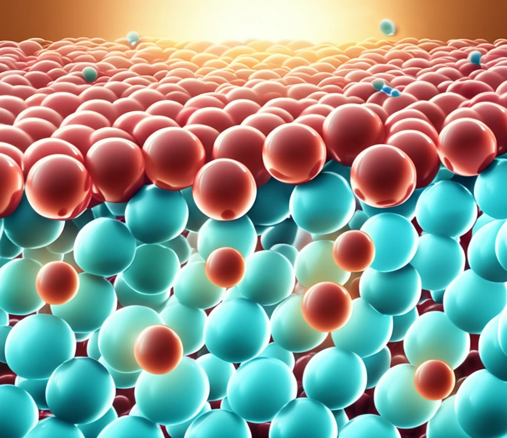
The catalyst layer in a PEMFC is a complex environment where oxygen, protons, and electrons converge to generate electricity. The efficiency of this process is heavily influenced by the catalyst layer's morphology – the arrangement and shape of its constituent particles. Imagine trying to build a high-performance engine; the way you arrange the components will significantly impact its power and fuel efficiency. The same principle applies to PEMFCs.
- Oxygen Transport: How easily oxygen can reach the reaction sites.
- Proton Transport: How effectively protons can move through the electrolyte film.
- Electrical Potential: The distribution of electrical potential within the catalyst layer.
- Current Density: The amount of electricity generated at the interface between the catalyst layer and the membrane.
Water Management and Flow Dynamics
Water management remains one of the most actively researched areas in PEM fuel cell development, as the membrane must stay hydrated while excess liquid water must be efficiently removed from the electrodes and flow channels. Recent reviews have addressed the full scope of PEM fuel cell technology development and its applications across transportation and stationary power sectors. Research into two-phase flow dynamics continues to advance understanding of gas-liquid interactions within proton exchange membrane fuel cells, including numerical simulations of three-dimensional gas and liquid two-phase flow behavior.
Durability Limits and Membrane Constraints
In PEM fuel cells, the membrane must be humidified, which limits air flow through the stack because excessive air will dry it out—requiring a separate reactant air supply and cooling system that complicates stack design. The durability and life-span of PEM fuel cells remain key barriers to large-scale automotive application, with pinhole formation in the membrane identified as a significant degradation pathway. Despite their promise, PEM fuel cells still face practical hurdles related to degradation under dynamic operating conditions, and the proton exchange membrane fuel cell remains an ideal automotive power source only in principle until these durability challenges are resolved.
Flow Plate Designs and System Comparisons
Research comparing different PEM fuel cell flow plate geometries, such as double-channel designs versus open pore cellular foam plates, highlights how flow distribution significantly impacts cell performance and current distribution uniformity. For extended-duration power delivery over a 72-hour excursion, a fuel cell system weighing only 15 pounds compared favorably to 29 pounds of batteries required for the same energy output, demonstrating a substantial weight advantage for longer missions. In residential applications, Japan's ENE-FARM program has installed over 400,000 proton exchange membrane fuel cell units since 2009 for combined heat and power generation, making it the largest deployed residential fuel cell fleet worldwide.
The Road Ahead: Designing the Future of Fuel Cells
This research offers valuable insights for designing more efficient and reliable PEMFCs. By understanding how catalyst layer morphology affects fuel cell performance, engineers can tailor the structure of these layers to optimize oxygen transport, proton conductivity, and current generation. This could lead to significant improvements in the range, performance, and cost-effectiveness of electric vehicles powered by fuel cells, accelerating the transition to a cleaner and more sustainable transportation future. The key is finding the right balance between effective diffusivity and maximizing the reactive surface area within the catalyst layer.
Efficiency and Market Trajectory
PEM fuel cell research, development, and demonstration activities have been steadily increasing worldwide, with targets being set to replace internal combustion engines in road transport. In controlled testing, a PEM fuel cell operating with ultra-high purity hydrogen at a flow rate of 450 mL/min and a 20 W load achieved a peak electrical power output of 31.588 W with an efficiency of 69.80%, indicating significant potential when operating under optimal conditions. Mathematical modeling of single-cell PEMFC performance under counter flow arrangements has advanced understanding of current density distribution and hydrogen consumption patterns, informing next-generation stack designs.
Market Growth and Segment Dominance
The MEA and PEM fuel cell market is segmented primarily by product types including 0-1 KW, 1-4 KW, and above 4 KW systems, with different power classes serving distinct application domains. Proton exchange membrane fuel cells held the largest market share in the global MEA and PEM fuel cell market in 2024, accounting for approximately 70 percent of the total market. PEMFCs also dominate the hydrogen fuel cell vehicle market specifically, representing 41.9 percent of vehicle segment share, driven by their high efficiency, compact design, and quick start-up capabilities.
Infrastructure, Standards, and Expanding Applications
Proton exchange membrane fuel cells have emerged as the frontrunner for residential applications, with hydrogen fuel cell systems positioned to power homes of the future by providing clean, decentralized electricity generation. Regulatory standards and certifications for PEM fuel cell components, including gas diffusion layers, vary by region and must address requirements for safety, performance, and environmental compliance. India's deployment of its first indigenous hydrogen fuel cell passenger vessel demonstrates the technology's expanding reach into maritime transport, where the electrochemical reaction generates electricity directly from hydrogen without combustion.
Field Deployments and Engineering Realities
PEM technology's solid proton-exchange membrane physically separates hydrogen and oxygen, eliminating an entire purification stage for laboratories, fuel-cell vehicles, and synthesis reactors while enabling compact, high-density stack designs for green hydrogen production. In real-world power electronics integration, dedicated power converters must be developed and optimized for fuel cell applications, requiring engineers to develop a thorough understanding of fuel cell operation characteristics. The performance of high-temperature PEM fuel cells is sensitive to ambient temperature variations, with studies modeling behavior across conditions ranging from 10°C to 40°C ambient while maintaining constant stack operating temperatures of 150°C.